Recently picked up a Japanese-market Korg 01/W Pro in mint condition with lots of custom-programed diskettes, cables, and hardcopy of the original service manual in Japanese. The unit looks almost new. The issue is that the power label on the back of the 01/W Pro, lists the following:
100V 50/60Hz 20W. No guarantee is applied when used outside Japan.
But I'm in the US. Any suggestions? Or should I just reach out to Korg Tech Support? I'm not even going to attempt to plug-n-play. Should I open it up and what should I look for?
Thanks.
Japanese-market Korg 01/W Pro in USA
Moderators: Sharp, X-Trade, Pepperpotty, karmathanever
Re: Japanese-market Korg 01/W Pro in USA
As far as I know...
The power transformer primary winding has taps for 100/117/220/230/240 volts. The AC common connection is at one end, with the taps following. For US operation the hot lead should be moved from the 100V tap to the 117V one. The fuse values are the same for AC voltages of 100~120V.
It appears that a PDF version of the SM is available here:
https://elektrotanya.com/korg_keyboard- ... nload.html
If you are uncomfortable with doing the 100-to-117V conversion yourself, then you could get a 120-to-100V step-down transformer. Korg claims only 20 Watt power consumption, so the step-down transformer can be relatively small - 100W ones are commonly available and inexpensive.
Korg: T3EX, 05R/W | Yamaha: Motif XF6 and XS6, A3000V2, A4000, YS200 | Fender Chroma Polaris | Roland U-220 | Etc.
The power supply for the Japanese market 01/W Pro is unusual, in that the incoming mains passes through a mains transformer that then supplies a switched mode power supply. The mains transformer has tappings for 100V, 117V, 220V, 230V, and 240V. For use in the US, set the tapping to 117V, or get a tech to do this for you.
.
.
-
MrRobertKrimson
- Posts: 27
- Joined: Wed Aug 26, 2015 6:39 pm
I appreciate both replies, gentlemen! I'm going to study the PDF, but I'm also going to make some calls locally to check on tech fees. I've replaced keys, batteries, and buttons on M1s, N264/N364s, and a few Trinity workstations, so I'm assuming it's nothing complicated. A part of me wants to plug-in that baby, but I just don't want to take a risk. Once I get it going, I'll give you all an update.
Looking at the schematic, the transformer feeds two linear regulated supply circuits, and not a switched mode supply, so ignore the mention of a switched mode supply in my previous posting.
Unhelpfully, the transformer pins are not labelled and, in the schematic, they are incorrectly labelled, in relation to the voltage setting positions shown on the primary winding of the transformer.
Unhelpfully, the transformer pins are not labelled and, in the schematic, they are incorrectly labelled, in relation to the voltage setting positions shown on the primary winding of the transformer.
There are some images on the web which might help.
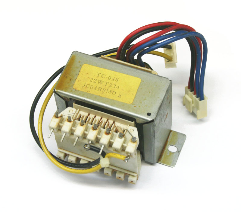
Here is an image of the transformer supplied by Syntaur. They are a US-based company, so wired for 117V, perhaps?:
From: https://syntaur.com/keyboard.php?keyboa ... model=01/W
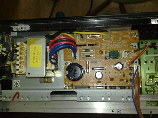
And another from a Chech company, wired for 230V?:
From: https://keyboardservis.cz/keyboard-inst ... org-01wfd/
The yellow and black wires are the incoming mains supply to the synth. The yellow wire is almost certainly connected to the transformer common terminal. Based on this, it is likely that the transformer pin assignments, shown in the first image, from left to right, are as follows:
240V
230V
220V
117V
100V
N/C (Not connected)
Common
Measuring the resistance (with the mains supply disconnected), between the Common pin and each of the other transformer pins, would be useful in verifying that this is indeed the case. 240V pin to common should have the highest resistance, 230V to common slightly less, and so on. Common pin to the 100V pin should give the lowest resistance.
.
Here is an image of the transformer supplied by Syntaur. They are a US-based company, so wired for 117V, perhaps?:
From: https://syntaur.com/keyboard.php?keyboa ... model=01/W
And another from a Chech company, wired for 230V?:
From: https://keyboardservis.cz/keyboard-inst ... org-01wfd/
The yellow and black wires are the incoming mains supply to the synth. The yellow wire is almost certainly connected to the transformer common terminal. Based on this, it is likely that the transformer pin assignments, shown in the first image, from left to right, are as follows:
240V
230V
220V
117V
100V
N/C (Not connected)
Common
Measuring the resistance (with the mains supply disconnected), between the Common pin and each of the other transformer pins, would be useful in verifying that this is indeed the case. 240V pin to common should have the highest resistance, 230V to common slightly less, and so on. Common pin to the 100V pin should give the lowest resistance.
.
-
MrRobertKrimson
- Posts: 27
- Joined: Wed Aug 26, 2015 6:39 pm
Yes, the Syntaur image shows wiring connected for US operation (117V tap). Yellow is indeed common, although it doesn't directly go to the transformer winding - it connects to an internal thermal fuse, which in turn connects to the winding at the N/C terminal.
The black hot lead on a 100V unit would be connected to the first pin beyond where the yellow is connected, and for US operation should be moved to the next one further up as in the Syntaur image.
As voip suggested, checking the primary winding resistances should verify the pinout.
--------------------
This won't affect the 100-to-117V conversion, but here's a puzzler...
Why (according to Korg) are the transformer secondary fuse values supposed to be different for 100~117V operation versus 220~240V? Obviously the primary fuse value should reflect the fact that half the mains current is required at 230V versus 117V, but once that's taken into account, the secondary current requirements should be determined by the draw of the rest of the synth and not related to the primary configuration. Anyone got a clue?
Korg: T3EX, 05R/W | Yamaha: Motif XF6 and XS6, A3000V2, A4000, YS200 | Fender Chroma Polaris | Roland U-220 | Etc.
The differing recommended secondary fuse values for 100-120 vs 220-240V make no sense at all, from a basic design standpoint. The incorrect labelling order of the transformer primary taps in the schematic, is also curious. It might just be that something got a little confused in conversation in one of the design team meetings, and wasn't picked up before the schematic was released. Who knows?
.
.